Sunday, April 24, 2016

Week 14

Video 1:


This video describes the process of what currently happens when our groups Rube Goldberg Machines are connected.  Both circuits are started and finished with dominoes in order to give us flexibility within our group and in regards to the groups around us.


Video 2:


Video's two and three provide examples of our failures.  Initially, we took it upon ourselves as a challenge to use only one power supply (since they're so sought after for this project)! During the process of setting up our machine, we had to overcome some obstacles.  We learned about where to position our different structures and what order we needed to place everything.   Despite what we learned, we still experienced random error where suddenly one circuit would just stop working.  On our next attempt, we finally noticed the power supply changing upon the switching of the first circuit.  Between both circuits sharing one power supply, we were drawing too much to run our machine %100 of the time.

Video 3:


Video 4: It worked!
After switching to two power supplies, we found it rather easy to make it work! 

Sunday, April 17, 2016

Week 13

Week 13

Stocker Rube Goldberg

     Parts Used

  • Seven Segment Display
  • LM324 Op Amp
  • Relay
  • Transistor 
  • Motor
  • Capacitors
  • Resistors: Various Ohm Values
  • Dominoes
  • Solar panel
  • Timer
  • Counter
  • Logic Gates

Rube Goldberg Plan

      The setup I have chosen to use consists of seven segment displays, a relay, op amp, transistor, motor and dominoes. The plan is to get voltage from my partner next to me to flip the relay. I haven't figured out how I will get my voltage to start from his rube goldberg. I was thinking of using a solar panel like the project in front of me who I will have to connect with. From there it will light up the seven segment displays and go into the op amp. I plan on having around 1 volts go into the op amp and around 10 come out by using resistors to get a gain of 10. From the output of the op amp it will be sent to the transistor to power the motor. The motor will be used to spin and hit the first domino to create a domino effect. I will have the dominoes go up and over the desk to fall down to the other side. The person I will be connecting with will be using a solar panel and will have it covered by a sheet of paper. With the dominoes I will be able to pull off the sheet to get his circuit going. In my video it isn't exactly ten seconds because my second set of dominoes are two hours away and I wasn't fully able to get it to the time limit. Once I get my second set of dominoes I will be able to add a longer setup.


Update: I am currently working on extending the time of my circuit by adding a timer along with a counter to set off my RB process. I will have the timer be hooked up to the segment displays and once it hits a certain amount of time, it will be transferred to the opamp and relay to start the motor. 

Group Project:

Nicks circuit did not work out the way he planned and a part failed on Friday. We weren't able to produce a video of our setups connecting but it will be done by using dominoes. Once his motor goes off after his timer is reached his goal time it will cause the dominoes to fall and pull the sheet off my solar panel. Once the sheet is pulled off from my solar panel, my project will start its process. 


Sunday, April 10, 2016

week 12

Week 12

Stocker Rube Goldberg

     Parts Used

  • Seven Segment Display
  • LM324 Op Amp
  • Relay
  • Transistor 
  • Motor
  • Resistors: Various Ohm Values
  • Dominoes

Rube Goldberg Plan

      The setup I have chosen to use consists of seven segment displays, a relay, op amp, transistor, motor and dominoes. The plan is to get voltage from my partner next to me to flip the relay. I haven't figured out how I will get my voltage to start from his rube goldberg. I was thinking of using a solar panel like the project in front of me who I will have to connect with. From there it will light up the seven segment displays and go into the op amp. I plan on having around 1 volts go into the op amp and around 10 come out by using resistors to get a gain of 10. From the output of the op amp it will be sent to the transistor to power the motor. The motor will be used to spin and hit the first domino to create a domino effect. I will have the dominoes go up and over the desk to fall down to the other side. The person I will be connecting with will be using a solar panel and will have it covered by a sheet of paper. With the dominoes I will be able to pull off the sheet to get his circuit going. In my video it isn't exactly ten seconds because my second set of dominoes are two hours away and I wasn't fully able to get it to the time limit. Once I get my second set of dominoes I will be able to add a longer setup.


Failures

       When it comes to using dominoes it is very easy to fail and knock them over. It happened to me a few times and also when the dominoes had to fall off the edge shown in my first video, the domino path didn't continue. Other failures involved the circuit with not putting in the correct resistor values to create the desired gain for the op amp. Also the resistor values for the transistor were off making the motor spin very slow and not hitting the domino over. 


Monday, March 28, 2016

Week 11

Blog sheet Week 11: Strain Gauges
Part A: Strain Gauges:
Strain gauges are used to measure the strain or stress levels on the materials. Alternatively, pressure on the strain gauge causes a generated voltage and it can be used as an energy harvester. You will be given either the flapping or tapping type gauge. When you test the circle buzzer type gauge, you will lay it flat on the table and tap on it. If it is the long rectangle one, you will flap the piece to generate voltage.
1.       Connect the oscilloscope probes to the strain gauge. Record the peak voltage values (positive and negative) by flipping/tapping the gauge with low and high pressure. Make sure to set the oscilloscope horizontal and vertical scales appropriately so you can read the values. DO NOT USE the measure tool of the oscilloscope. Adjust your oscilloscope so you can read the values from the screen. Fill out Table 1 and provide photos of the oscilloscope.


Table 1: Strain gauge characteristics
Flipping strength
Minimum Voltage
Maximum Voltage
Low
        -380mV
4V
High
1V
35V

2.       Press the “Single” button below the Autoscale button on the oscilloscope. This mode will allow you to capture a single change at the output. Adjust your time and amplitude scales so you have the best resolution for your signal when you flip/tap your strain gauge. Provide a photo of the oscilloscope graph.


Part B: Half-Wave Rectifiers
1.       Construct the following half-wave rectifier. Measure the input and the output using the oscilloscope and provide a snapshot of the outputs.
2.       Calculate the effective voltage of the input and output and compare the values with the measured ones by completing the following table.

Effective (rms) values
Calculated
Measured
Input
3.536V
3.535V
Output
1.5916V
1.696V


3.       Construct the following circuit and record the output voltage using both DMM and the oscilloscope.

Oscilloscope
DMM
Output Voltage (p-p)
.848V
Not Possible
Output Voltage (mean)
1.72V

Not Possible

4.       Replace the 1 µF capacitor with 100 µF and repeat the previous step. What has changed?

Since no 100 ÂµF capacitor was available, we were provided with a 470 ÂµF capacitor.  This is a much larger capacitor and means that we would not see the cap discharge at 1KHz.  In order to fix this we had to turn the frequency down.  In this case we used 6.3 Hz. 


Oscilloscope
DMM
Output Voltage (p-p)
920mv
Not Possible
Output Voltage (mean)
5.67V

Not Possible


Part C: Energy Harvesters
1.       Construct the half-wave rectifier circuit without the resistor but with the 1 µF capacitor. Instead of the function generator, use the strain gauge. Discharge the capacitor every time you start a new measurement. Flip/tap your strain gauge and observe the output voltage. Fill out the table below:
Tap frequency
Duration
Output voltage
1 flip/second
10 seconds
5.64 V 
1 flip/second
20 seconds
5.8 V
1 flip /second
30 seconds
6.5 V
4 flips/second
10 seconds
5.72 V
4 flips/second
20 seconds
5.98 V
4 flips/second

10 flips/sec
30 seconds

10 sec
7.3 V

10.4 V

2.       Briefly explain your results.

The flips on the strain gauge greatly affected the amount the capacitor was charging. With the more flips per second the faster the voltage went up across the capacitor. We even added a higher flip rate just to observe what will happen and the voltage was greatly increased. 


3.       If we do not use the diode in the circuit (i.e. using only strain gauge to charge the capacitor), what would you observe at the output? Why?

Without the diode it doesnt work as well because the circuit is not a half wave rectifier anymore. The diode is needed for the rectifier circuit. 


Friday, March 25, 2016

Week 10

Blogsheet week 10

In this week’s lab, you will collect more data on low pass and high pass filters and “process” them using MATLAB.
PART A: MATLAB practice.
1.       Open MATLAB. Open the editor and copy paste the following code. Name your code as FirstCode.m
Save the resulting plot as a JPEG image and put it here.
clear all;
close all;
x = [1 2 3 4 5];
y = 2.^x;
plot(x, y, 'LineWidth', 6)
xlabel('Numbers', 'FontSize', 12)
ylabel('Results', 'FontSize', 12)


2.       What does clear all do?
This clears all previous data held in Matlab currently.
3.       What does close all do?
Closes any windows currently open. 
4.       In the command line, type x and press enter. This is a matrix. How many rows and columns are there in the matrix?
There are five rows and one column.
5.       Why is there a semicolon at the end of the line of x and y?
This signifies the end of the line of code. 
6.       Remove the dot on the y = 2.^x; line and execute the code again. What does the error message mean?
“Error using  ^
Inputs must be a scalar and a square matrix.
To compute elementwise POWER, use POWER (.^) instead.”

7.       How does the LineWidth affect the plot? Explain.
It makes the width of the plot line wider.  For example, the original line width was 6.  The following image is the same plot using a line width of 30.


8.       Type help plot on the command line and study the options for plot command. Provide how you would change the line for plot command to obtain the following figure (Hint: Like ‘LineWidth’, there is another property called ‘MarkerSize’)
We would add “'-or','MarkerSize', 12” to the code.  Where “-or” signifies making the plot red and the ‘MarkerSize, 12” code make the markers large.

9.       What happens if you change the line for x to x = [1; 2; 3; 4; 5]; ? Explain.
Nothing changes.  The graph stays the same both times. 
10.   Provide the code for the following figure. You need to figure out the function for y. Notice there are grids on the plot.
11.   Degree vs. radian in MATLAB:
a.       Calculate sinus of 30 degrees using a calculator or internet.
Sin(30) = 0.5
b.      Type sin(30) in the command line of the MATLAB. Why is this number different? (Hint: MATLAB treats angles as radians).
The answer of radians is (-0.9880).  This is because it’s in radians. 
c.       How can you modify sin(30) so we get the correct number?
We can convert 30 degrees into radians by multiplying by pi an divide by 180.
12.   Plot y = 
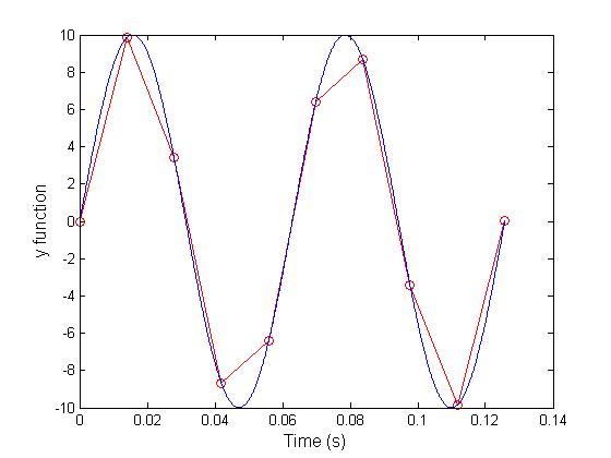
10 sin (100 t) using Matlab with two different resolutions on the same plot: 10 points per period and 1000 points per period. The plot needs to show only two periods. Commands you might need to use are linspace, plot, hold on, legend, xlabel, and ylabel. Provide your code and resulting figure. The output figure should look like the following:

clear all;
close all;
t = linspace(0,((4*pi)/100),10);
x = 10*sin(100*t);
f = linspace(0,((4*pi)/100),1000);
y = 10*sin(100*f);


plot(t,x, '-or');
hold on;
plot(f,y);
xlabel('Time (s)', 'FontSize', 12)
ylabel('y function', 'FontSize', 12)

And our graph:

13.   Explain what is changed in the following plot comparing to the previous one.
The fine graph is clipped at a maximum positive amplitude of 5.

14.   The command find was used to create this code. Study the use of find (help find) and try to replicate the plot above. Provide your code.
clear all;
close all;
t = linspace(0,((4*pi)/100),10);
x = 10*sin(100*t);

f = linspace(0,((4*pi)/100),1000);
y = 10*sin(100*f);
y(find(y > 5)) = 5;


plot(t,x, '-or');
hold on;
plot(f,y);
xlabel('Time (s)', 'FontSize', 12)
ylabel('y function', 'FontSize', 12)

Our Image:


15.   Create a code that would clip the negative part of the sinusoidal signal for the fine plot to -5.
clear all;
close all;
t = linspace(0,((4*pi)/100),10);
x = 10*sin(100*t);

f = linspace(0,((4*pi)/100),1000);
y = 10*sin(100*f);
y(find(y < -5)) = -5;


plot(t,x, '-or');
hold on;
plot(f,y);
xlabel('Time (s)', 'FontSize', 12)

ylabel('y function', 'FontSize', 12)


PART B: Filters and MATLAB
1.       Build a low pass filter using a resistor and capacitor in which the cut off frequency is 1 kHz. Observe the output signal using the oscilloscope. Collect several data points particularly around the cut off frequency. Provide your data in a table.


2.       Plot your data using MATLAB. Make sure to use proper labels for the plot and make your plot line and fonts readable. Provide your code and the plot.
x = [5 10 20 30 40 50 100 200 300 400 500 600 700 800 900 1000 1100 1200 1300 1400 2000 3000 4000];
y = [4.72 4.23 3.14 2.4 1.9 1.56 .83 .420 .292 .222 .180 .156 .136 .126 .114 .103 .098 .091 .082 .077 .061 .048 .040];
plot(x, y,'g', 'LineWidth', 6)
xlabel('Frequency ', 'Fontsize', 12)
ylabel('V Peak ','FontSize', 12)
hold on;


3.       Calculate the cut off frequency using MATLAB. find command will be used. Provide your code.

x = [5 10 20 30 40 50 100 200 300 400 500 600 700 800 900 1000 1100 1200 1300 1400 2000 3000 4000];
y = [4.72 4.23 3.14 2.4 1.9 1.56 .83 .420 .292 .222 .180 .156 .136 .126 .114 .103 .098 .091 .082 .077 .061 .048 .040];
plot(x, y,'g', 'LineWidth', 6)
xlabel('Frequency ', 'Fontsize', 12)
ylabel('V Peak ','FontSize', 12)
hold on;
t=find(y==400);
x(t)


4.       Put a horizontal dashed line on the previous plot that passes through the cutoff frequency.


5.       Repeat 1-3 by modifying the circuit to a high pass filter.


 x = [100 300 600 900 1200 1500 1800 2100 2400 2700 3000 3300 3600 3900 4200 4500 4800 9000 12000 17000 20000];
y = [0.47 .872 1.47 2.12 3.1 3.89 4.32 4.57 4.82 5.877 6.39 8.11 8.72 8.72 8.72 8.72 8.72 8.72 8.72 8.72 8.72];
plot(x, y, 'LineWidth', 6)
xlabel('Frequency ', 'Fontsize', 12)
ylabel('V Peak ','FontSize', 12)
hold on;


6.       Repeat #4 for #5.