Blog sheet week 5
1.
Functional check: Oscilloscope manual page 5.
Perform the functional check (photo).
2.
Perform manual probe compensation (Oscilloscope
manual page 8) (Photo of overcompensation and proper compensation).


Overcompensation

Undercompensation

Proper Compensation

3.
What does probe attenuation (1x vs 10x) do
(Oscilloscope manual page 9)?
The attenuation factor affects the vertical scale of the signal. When the probe is set to the 1X setting the bandwidth is limited to only 7Mhz. By switching to the 10X setting it is possible to get the full bandwidth of the probe.
The attenuation factor affects the vertical scale of the signal. When the probe is set to the 1X setting the bandwidth is limited to only 7Mhz. By switching to the 10X setting it is possible to get the full bandwidth of the probe.
4.
How do vertical and horizontal controls work?
Why would you need it (Oscilloscope manual pages 34-35)?
For the horizontal position on the oscilloscope it establishes the time between the trigger and the screen center. For the vertical controls we are able to scale the waveforms for volts/div on channels 1,2,3 and 4. Also the vertical position of the waveform can be adjusted with the controls.
For the horizontal position on the oscilloscope it establishes the time between the trigger and the screen center. For the vertical controls we are able to scale the waveforms for volts/div on channels 1,2,3 and 4. Also the vertical position of the waveform can be adjusted with the controls.
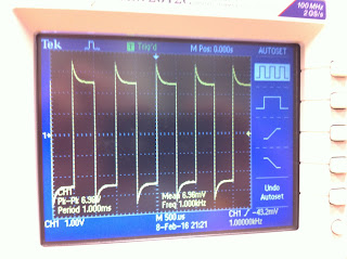
5.
Generate a 1 kHz, 1 Vpp around a DC 2 V from the
function generator (use the output connector). DO NOT USE oscilloscope probes for the function generator. There is
a separate BNC cable for the function generator.
a.
Connect this to the oscilloscope and verify the
input signal using the horizontal and vertical readings (photo).


b.
Figure out how to measure the signal properties
using menu buttons on the scope.
The menu buttons allow us to see the frequency, period, voltages and more.
The menu buttons allow us to see the frequency, period, voltages and more.
6.
Connect function generator and oscilloscope
probes switched (red to black, black to red). What
happens? Why?
No signal displays on the oscilloscope. The signal is no longer travelling through the scope, but rather, is being passed to ground.
happens? Why?
No signal displays on the oscilloscope. The signal is no longer travelling through the scope, but rather, is being passed to ground.
7.
After calibrating the second probe, implement the
voltage divider circuit below. Measure the following voltages using the
Oscilloscope and comment on your results:
a.
Va and Vb at the same time
(Photo)
b.
Voltage across R4.

The resistance across R4 was measured at 240mv-119mV giving a value of 121mV.
8.
For the same circuit above, measure Va
and Vb using the handheld DMM both in AC and DC mode. What are your
findings? Explain.
AC
Va= .092mV
Vb=0.182mV
DC
Va=17.8 mV
Vb=34.2mV
The measurements from the circuit for Vb are about double the measurement of Va. Since the resistors are the same they will use the same amount of voltage.
9.
For the circuit below
a.
Calculate R so given voltage values are
satisfied. Explain your work (video)
Hand Calculation
Converting the 5V rms to peak voltage it is possible to calculate the resistance so the voltage values are satisfied at 6.07k.
b.
Construct the circuit and measure the values
with the DMM and oscilloscope (video). Hint: 1kΩ cannot be probed directly by
the scope. But R6 and R7 are in series and it does not matter which one is
connected to the function generator.
Oscilloscope Reading
Circuit DMM reading
Oscilloscope Reading
10.
Operational amplifier basics: Construct the
following circuits using the pin diagram of the opamp. The half circle on top
of the pin diagram corresponds to the notch on the integrated circuit (IC).
Explanations of the pin numbers are below:
1: DO NOT USE
|
8: DO NOT USE
|
2: Negative input
|
7: +10V
|
3: Positive input
|
6: output
|
4: -10 V
|
5: DO NOT USE
|
a.
Inverting amplifier: Rin = 1kΩ, Rf
= 5kΩ (do not forget -10 V and +10
V). Apply 1 Vpp @ 1kHz. Observe input and output at the same time.
What happens if you slowly increase the input voltage up to 5 V? Explain your
findings. (Video)
Inverting Amplifier
Inverting Amplifier Waveform
Slowly increasing the voltage will saturate the circuit and the waveform will begin to square off.
b.
Non-inverting amplifier: R1 = 1kΩ, R2
= 5kΩ (do not forget -10 V and +10
V). Apply 1 Vpp @ 1kHz. Observe input and output at the same time.
What happens if you slowly increase the input voltage up to 5 V? Explain your
findings. (Video)
Non Inverting Amplifier Waveform
Slowly increasing the voltage will saturate the circuit and the waveform will begin to square off.
Non Inverting Amplifier
Non Inverting Amplifier Waveform
Slowly increasing the voltage will saturate the circuit and the waveform will begin to square off.
Maybe its just me but isn't there supposed to be pictures and videos and answers and things on this blog
ReplyDeleteIt leaves a lot to be imagined. Very solipsistic, I like it!
ReplyDelete#3 has some missing information.
ReplyDelete#8: Are AC and DC calculations related?
Respond to your comments, even if they are teasing you!