Blogsheet week 6
Operational Amplifiers
Explanations of the pin numbers are below:
1: DO NOT USE
|
8: DO NOT USE
|
2: Negative input
|
7: +10V
|
3: Positive input
|
6: output
|
4: -10 V
|
5: DO NOT USE
|
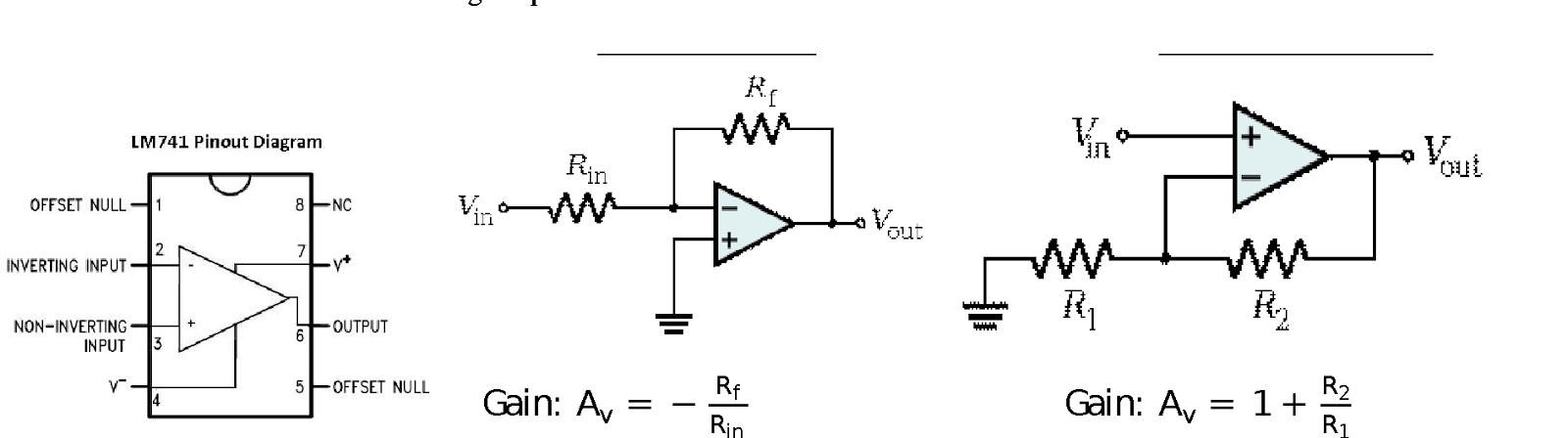
1. You will use the OPAMP in “open-loop” configuration in this part, where input signals will be applied directly to the pins 2 and 3.
- Apply 0 V to the inverting input. Sweep the non-inverting input (Vin) from -10 V to 10 V with 1 V steps. Take more steps around 0 V (both positive and negative). Create a table for Vin and Vout. Plot the data (Vout vs Vin). Discuss your results. What would be the ideal plot? Table OneVinVout-10 V-3.719 V-7 V-3.72 V-5 V-3.72 V-3 V-3.72 V-1 V-3.72 V-0.5 V-3.72 V0 V-3.72 V0.5 V4.44 V1 V4.44 V3V4.44 V5 V4.44 V7 V4.44 V10 V4.44 VTable-1
 Graph-1

- Apply 0 V to the non-inverting input. Sweep the inverting input (Vin) from -10 V to 10 V with 1 V steps. Take more steps around 0 V (both positive and negative). Create a table for Vin and Vout. Plot the data (Vout vs Vin). Discuss your results. What would be the ideal plot? Table Two
VinVout-10 V4.44 V-7 V4.44 V-5 V4.44 V-3 V4.44 V-1 V4.44 V-0.5 V4.44 V0 VN/A0.5 V-3.7 V1 V-3.7 V3V-3.7 V5 V-3.7 V7 V-3.7 V10 V-3.7 VTable-2 Graph-2

- Create a non-inverting amplifier. (R2 = 2 kΩ, R1 = 1 kΩ). Sweep Vin from -10 V to 10 V with 1 V steps. Create a table for Vin and Vout. Plot the measured and calculated data together. Table ThreeVinVoutVinVout-10 V-3.61 V0.5 V1.48 V-9 V-3.61 V1 V2.966 V-8 V-3.61 V2 V4.2 V-7 V-3.61 V3 V4.2 V-6 V-3.61 V4 V4.2 V-5 V-3.61 V5 V4.2 V-4 V-3.61 V6 V4.2 V-3 V-3.61 V7 V4.2 V-2 V-3.606 V8 V4.2 V-1 V-2.96 V9 V4.2 V-0.5 V-1.45 V10 V4.2 VTable-3

Graph-3

- Create an inverting amplifier. (Rf = 2 kΩ, Rin = 1 kΩ). Sweep Vin from -10 V to 10 V with 1 V steps. Create a table for Vin and Vout. Plot the measured and calculated data together. Table Four
Vin Vout Vin Vout -5 V4.15 V0.5 V-0.769 V-4 V4.14 V1 V-1.85 V-3 V4.16 V2 V-3.56 V-2 V3.94 V3 V-3.54 V-1 V1.52 V4 V-3.56 V-0.5 V1.13 V5 V-3.56 VTable-4 Graph-4

- Explain how an OPAMP works. How come is the gain of the OPAMP in the open loop configuration too high but inverting/non-inverting amplifier configurations provide such a small gain? An op amp works by taking two input signals and producing an output signal. Ideally, for the op amp, both inputs would be the same, however, as the inputs differ, the amplifier tends to push the output towards infinity. As a result with no resistances or feedback, the gain can seem to change instantaneously. But the Op Amp will still be restricted by laws of conservation.
EGR 393 Temperature Controlled LED System
Tips:
1. If something is not working, check your connection first.
2. Check the pins carefully, LM35 is VERY easy to be burned if you connect the wrong pins.
3. Read the datasheet carefully.
4. Before starting to connect the circuit, try to sketch it on a paper first, make sure everything is clear.
Components:
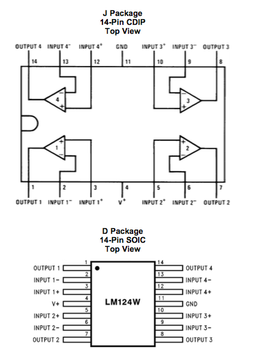
1. TMP36 Temperature Sensor 2. Lm324 Operational Amplifier 3. OMRON G8QN Relay 4. LED
Procedure:
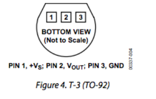
TMP36 Temperature Sensor: Pin layout – look up characteristics to calculate temperature from datasheet (under Bb/Week6).
Temperature Sensor: Put TMP36 temp sensor on breadboard.
- Connect the +VS to 5 volts and GND to ground.
- Using a voltage meter, measure the output voltage from the VOUT. Now put your finger (or cover the sensor with your palm) on the TMP36 temperature sensor for a while, observing how the output voltage changes. Check Fig. 6 in the data sheet (EXPLAIN). When we measured the voltage of the circuit at room temperature, we saw an output voltage of 0.71 V. When we heated it by hand, however, we saw an output voltage of 0.78 V. That's an increase of 0.07 volts just by covering it with one's hand.
Relay (Manual under Bb/Week6)
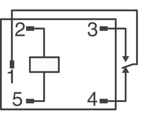
Pin 1 – Input voltage (amount of voltage sent to pins 3 or 4)
Pin 2 – Power supply
Pin 3 – Vout = Vin when Vin > Vthreshold
Pin 4 – Vout = Vin when Vin < Vthreshold
Pin 5 - GND
schematic view is the bottom view!
- Connect your DC power supply to pin 2 and ground pin 5. Set your power supply to 0V. Switch your multimeter to measure the resistance mode; use your multimeter to measure the resistance between pin 4 and pin 1. Do the same measurement between pin 3 and pin 1. Explain your findings (EXPLAIN). Between pins 1 and 4 we saw a resistance of 1 ohm. We saw no available measurement between pins 3 and 1. This makes sense. If the relay is switched to one position, the other should not be conducting between the pins and thus would not give us a resistance.
- Now sweep your DC power supply from 0V to 8V and back to 0V. What do you observe at the multimeter (resistance measurements similar to #1)? Did you hear a clicking sound? How many times? What is the “threshold voltage values” that cause the “switching?” (EXPLAIN with a VIDEO).
Relay Click
- How does the relay work? Apply a separate DC voltage of 5 V to pin 1. Check the voltage value of pin 3 and pin 4 (each with respect to ground) while switching the relay (EXPLAIN with a VIDEO).
Pin 3
Pin 4
LED + Relay
- Connect positive end of the LED diode to the pin 3 of the relay and negative end to a 100 ohm resistor. Ground the other end of the resistor. Negative end of the diode will be the shorter wire.
- Apply 3 V to pin 1
- Turn LED on/off by switching the relay. Explain your results in the video. Draw the circuit schematic (VIDEO)
LED Light Up
Operational Amplifier (data sheet under Bb/week 6)
- Connect the power supplies to the op-amp (+10V and -10V). Show the operation of LM 124 operational amplifier in DC mode with a non-inverting amplifier configuration. Choose any opamp in the IC. Method: Use several R1 and R2 configurations and change your input voltage and record your output voltage. (EXPLAIN with a TABLE)
R1R2Vin1Vout1Vin2Vout22KΩ1KΩ1.2 V1.9 V6.5 V8.5 V120Ω1KΩ0.76 V7.3 V1.49 V8.36 VWe also experimented with a constant input of about 0.8V and a fair amount of different resistors in order to see what differences in voltage we might receive. We kept R2 as a constant 1KΩ to ensure that we would better understand the changes we made. Our goal was to find about 5.6 V output using around 0.8 V input. We used the following equation to make our estimations.This yielded a experimental R1 of about 160 Ω.
- Use your temperature sensor as your input. Do you think you can generate enough voltage to trigger the relay? (EXPLAIN) Not by itself. Even if we got it quite hot, we probably couldn't generate the right amount of voltage. The way to solve this is to use both the temperature sensor and the op amp. We did this using different values of resistance for R1. Our calculation in the previous task was a step in the right direction, however, we found that our output voltage while the temperature sensor was at room temperature was still too high. In order to solve this, we made R2 slightly bigger. At 150 Ω we were able to make it work and at 180 Ω we were able to make the relay trigger comfortably.
- Design a system where LED light turns on when you heat up the temperature sensor. (CIRCUIT schematic and explanation in a VIDEO)


Here's an image of one potential circuit that could be used to light the LED. We didn't build this exact circuit, however, the same (but more complex) idea can be seen in the next video. We set the temperature sensor to supply an input voltage to the OP amp which then amplified the voltage high enough to switch the relay which connected the LED through a 100 Ohm resistor to ground.
- BONUS! Show the operation of the entire circuit. (VIDEO)
Everything looks good! just gotta finish your videos nick and david!
ReplyDeleteI like the graphs and tables. I think that putting a quick description of what is happening with these graphs and tables makes it easier for us to understand why or how you got those numbers. Also gotta do the videos!!
ReplyDeleteThanks! videos are added just have to add some stuff for tables and graphs like you suggested. Final circuit video didnt save on my phone for some reason will have to come early to class to re take it
DeleteI like how you include screenshots from the blog sheet so your blog is organized and easy to read!
ReplyDeleteThanks Laura!
Delete#1 no explanations. (-2)
ReplyDelete#2, 3: Plot should have had the theoretical data as well. (-2)
#4 is not correct. We will talk about it though.
Bonus video! (+2)