Friday, February 26, 2016

Week 7

Blogsheet week 7
Digital Circuits
  1. Force sensing resistor gives a resistance value with respect to the force that is applied on it. Try different loads (Pinching, squeezing with objects, etc.) and write down the resistance values. (EXPLAIN with TABLE)


  1. 7 Segment display:
    1. Check the manual of 7 segment display. Pdf document’s page 5 (or in the document page 4) circuit B is the one we have. Connect pin 3 or pin 14 to 5 V. Connect a 330 Ω resistor to pin 1. Other end of the resistor goes to ground. Which line lit up? Using package dimensions and function for B (page 4 in pdf), explain the operation of the 7 segment display by lighting up different segments. (EXPLAIN with VIDEO).

Depending on what pin you put the resistor is is what will light up on the 7 segment display.

7 Segment Display Light Up


    1. Using resistors for each segment, make the display show 0 and 5. (EXPLAIN with PHOTOs)
Segment Display of Zero

Segment Display of Five


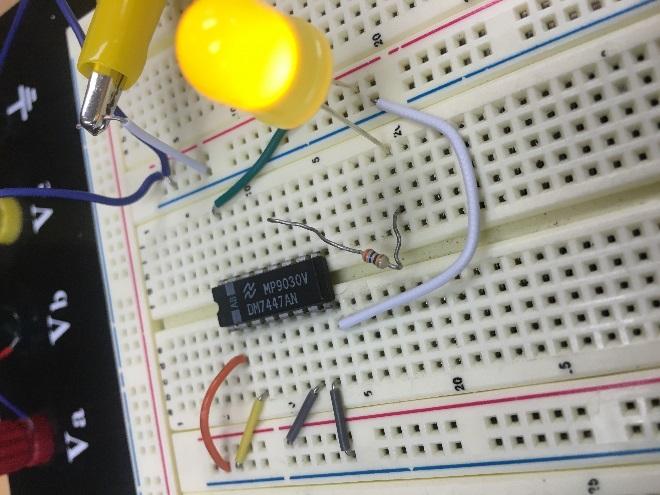
  1. Display driver (7447). This integrated circuit (IC) is designed to drive 7 segment display through resistors. Check the data sheet. A, B, C, and D are binary inputs. Pins 9 through 15 are outputs that go to the display. Pin 8 is ground and pin 16 is 5 V.
    1. By connecting inputs either 0 V or 5 V, check the output voltages of the driver. Explain how the inputs and outputs are related. Provide two different input combinations. (EXPLAIN with PHOTOs and TRUTH TABLE)
Truth Table

Binary Input of 0010


Binary Input of 0111


UPDATE! You cannot actually measure the output voltages directly (I challenge you to figure out why!). You need to connect an LED and a resistor. LED’s positive terminal will go to 5 V. Negative terminal will be connected to your outputs via a resistor. The circuit would look like below:
C:\Users\kaya2t\Dropbox\TEACHING\EGR 393\week 7\Photo Feb 23, 11 45 24 AM.jpg


    1. Connect the display driver to the 7 segment display. 330 Ω resistors need to be used between the display driver outputs and the display (a total of 7 resistors). Verify your question 3a outputs with those input combinations. (EXPLAIN with VIDEO)


7 Segment Display Connected to 7447


Input Combinations from 3a.


  1. 555 Timer:
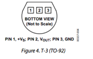
    1. Construct the circuit in Fig. 14 of the 555 timer data sheet. VCC = 5V. No RL (no connection to pin 3). RA = 150 kΩ, RB = 300 kΩ, and C = 1 µF (smaller sized capacitor). 0.01 µF capacitor is somewhat larger in size. Observe your output voltage at pin 3 by oscilloscope. (Breadboard and Oscilloscope PHOTOs)
Oscilloscope Waveform

Circuit Layout with 555 Timer


    1. Does your frequency and duty cycle match with the theoretical value? Explain your work.

The measured and calculated were fairly similar. The frequency was off more than the duty cycle. The calculated values can be seen above by using the equations written down. 


    1. Connect the force sensing resistor in series with RA. How can you make the circuit give an output? Can the frequency of the output be modified with the force sensing resistor? (Explain with VIDEO)
With the force sensing resistor added in series it is possible to get an output and also modify the frequency based on the amount of force added to the sensor.


Force Sensor


  1. Binary coded decimal (BCD) counter (74192). This circuit generates a 4-bit counter. With every clock change, output increases; 0000, 0001, 0010, …, 0111, 1000, 1001. But after 1001 (which is decimal 9), it goes back to 0000. That way, in decimal, it counts from 0 to 9. Outputs of 74192 are labelled as QA (Least significant bit), QB, QC, and QD (Most significant bit) in the data sheet (decimal counter, 74192). Use the following connections:
5 V: pins 4, 11, 16.
0 V (ground): pins 8, 14.
10 µF capacitor between 5 V and ground.

    1. Connect your 555 timer output to pin 5 of 74192. Observe the input and each output on the oscilloscope. (EXPLAIN with VIDEO and TRUTH TABLE)
555 Timer Inputs and Outputs


  1. 7486 (XOR gate). Pin diagram of the circuit is given in the logic gates pin diagram pdf file. Ground pin is 7. Pin 14 will be connected to 5 V. There are 4 XOR gates. Pins are numbered. Connect a 330 Ω resistor at the output of one of the XOR gates.
    1. Put an LED in series to the resistor. Negative end of the LED (shorter wire) should be connected to the ground. By choosing different input combinations (DC 0V and DC 5 V), prove XOR operation through LED. (EXPLAIN with VIDEO)

Based on the table from the 7447 part of the lab it is possible to pre determine when the light will be on based on the truth table.
XOR Implementation with 0V and 5V


    1. Connect XOR’s inputs to the BCD counters C and D outputs. Explain your observation. (EXPLAIN with VIDEO)

XOR Connected to BCD

    1. For 6b, draw the following signals together: 555 timer (clock), A, B, C, and D outputs of 74192, and the XOR output. (EXPLAIN with VIDEO)


  1. Connect the entire circuit: Force sensing resistor triggers the 555 timer. 555 timer’s output is used as clock for the counter. Counter is then connected to the driver (Counter’s A, B, C, D to driver’s A, B, C, D). Driver is connected to the display through resistors. XOR gate is connected to the counter’s C and D inputs as well and an LED with a resistor is connected to the XOR output. Draw the circuit schematic. (VIDEO and PHOTO)
The circuit is extremely messy and hard to see but this one was rushed. I had everything done and recorded but my phone broke and I lost all my videos and pictures.
Full Circuit 

Full Circuit Schematic(Messy)


  1. Using other logic gates provided (AND and OR), come up with a different LED lighting scheme. (EXPLAIN with VIDEO)
For the AND gates and with the truth table it is possible to either use C and D or A and B to determine when the light will turn on. For input A and B the light will turn on with an AND gate at 3 and 7. For inputs C and D the light wont turn on as the input never has 1 for C and 1 for D at the same time.
For the OR gate the lights will be off only at 0, 4 and 8 as they have values of 0 for both A and B.


                            AND Gate Inputs AB

OR Gates input AB


Friday, February 19, 2016

Blog Week 6

Blogsheet week 6
Operational Amplifiers
Explanations of the pin numbers are below:
1: DO NOT USE
8: DO NOT USE
2: Negative input
7: +10V
3: Positive input
6: output
4: -10 V
5: DO NOT USE
1. You will use the OPAMP in “open-loop” configuration in this part, where input signals will be applied directly to the pins 2 and 3.


  1. Apply 0 V to the inverting input. Sweep the non-inverting input (Vin) from -10 V to 10 V with 1 V steps. Take more steps around 0 V (both positive and negative). Create a table for Vin and Vout. Plot the data (Vout vs Vin). Discuss your results. What would be the ideal plot? Table One
    Vin
    Vout
    -10 V
    -3.719 V
    -7 V
    -3.72 V
    -5 V
    -3.72 V
    -3 V
    -3.72 V
    -1 V
    -3.72 V
    -0.5 V
    -3.72 V
    0 V
    -3.72 V
    0.5 V
    4.44 V
    1 V
    4.44 V
    3V
    4.44 V
    5 V
    4.44 V
    7 V
    4.44 V
    10 V
    4.44 V
    Table-1

    Graph-1

  1. Apply 0 V to the non-inverting input. Sweep the inverting input (Vin) from -10 V to 10 V with 1 V steps. Take more steps around 0 V (both positive and negative). Create a table for Vin and Vout. Plot the data (Vout vs Vin). Discuss your results. What would be the ideal plot? Table Two
    Vin
    Vout
    -10 V
    4.44 V
    -7 V
    4.44 V
    -5 V
    4.44 V
    -3 V
    4.44 V
    -1 V
    4.44 V
    -0.5 V
    4.44 V
    0 V
    N/A
    0.5 V
    -3.7 V
    1 V
    -3.7 V
    3V
    -3.7 V
    5 V
    -3.7 V
    7 V
    -3.7 V
    10 V
    -3.7 V
    Table-2
    Graph-2
  1. Create a non-inverting amplifier. (R2 = 2 kΩ, R1 = 1 kΩ). Sweep Vin from -10 V to 10 V with 1 V steps. Create a table for Vin and Vout. Plot the measured and calculated data together. Table Three
    Vin
    Vout
    Vin
    Vout
    -10 V
    -3.61 V
    0.5 V
    1.48 V
    -9 V
    -3.61 V
    1 V
    2.966 V
    -8 V
    -3.61 V
    2 V
    4.2 V
    -7 V
    -3.61 V
    3 V
    4.2 V
    -6 V
    -3.61 V
    4 V
    4.2 V
    -5 V
    -3.61 V
    5 V
    4.2 V
    -4 V
    -3.61 V
    6 V
    4.2 V
    -3 V
    -3.61 V
    7 V
    4.2 V
    -2 V
    -3.606 V
    8 V
    4.2 V
    -1 V
    -2.96 V
    9 V
    4.2 V
    -0.5 V
    -1.45 V
    10 V
    4.2 V
    Table-3

    Graph-3


  1. Create an inverting amplifier. (Rf = 2 kΩ, Rin = 1 kΩ). Sweep Vin from -10 V to 10 V with 1 V steps. Create a table for Vin and Vout. Plot the measured and calculated data together. Table Four
    Vin Vout Vin Vout
    -5 V
    4.15 V
    0.5 V
    -0.769 V
    -4 V
    4.14 V
    1 V
    -1.85 V
    -3 V
    4.16 V
    2 V
    -3.56 V
    -2 V
    3.94 V
    3 V
    -3.54 V
    -1 V
    1.52 V
    4 V
    -3.56 V
    -0.5 V
    1.13 V
    5 V
    -3.56 V
    Table-4
    Graph-4


  1. Explain how an OPAMP works. How come is the gain of the OPAMP in the open loop configuration too high but inverting/non-inverting amplifier configurations provide such a small gain? An op amp works by taking two input signals and producing an output signal. Ideally, for the op amp, both inputs would be the same, however, as the inputs differ, the amplifier tends to push the output towards infinity. As a result with no resistances or feedback, the gain can seem to change instantaneously. But the Op Amp will still be restricted by laws of conservation.
EGR 393 Temperature Controlled LED System

Tips:

1. If something is not working, check your connection first.
2. Check the pins carefully, LM35 is VERY easy to be burned if you connect the wrong pins.
3. Read the datasheet carefully.
4. Before starting to connect the circuit, try to sketch it on a paper first, make sure everything is clear.

Components:

1. TMP36 Temperature Sensor 2. Lm324 Operational Amplifier 3. OMRON G8QN Relay 4. LED

Procedure:


Macintosh HD:Users:Katherine:Desktop:Screen Shot 2015-12-07 at 9.09.58 PM.png
TMP36 Temperature Sensor: Pin layout – look up characteristics to calculate temperature from datasheet (under Bb/Week6).

Temperature Sensor: Put TMP36 temp sensor on breadboard.
  • Connect the +VS to 5 volts and GND to ground.
  • Using a voltage meter, measure the output voltage from the VOUT. Now put your finger (or cover the sensor with your palm) on the TMP36 temperature sensor for a while, observing how the output voltage changes. Check Fig. 6 in the data sheet (EXPLAIN). When we measured the voltage of the circuit at room temperature, we saw an output voltage of 0.71 V. When we heated it by hand, however, we saw an output voltage of 0.78 V. That's an increase of 0.07 volts just by covering it with one's hand.

Relay (Manual under Bb/Week6)
Macintosh HD:Users:Katherine:Desktop:Screen Shot 2015-12-07 at 9.33.00 PM.png
Pin 1 – Input voltage (amount of voltage sent to pins 3 or 4)
Pin 2 – Power supply
Pin 3 – Vout = Vin when Vin > Vthreshold
Pin 4 – Vout = Vin when Vin < Vthreshold
Pin 5 - GND
schematic view is the bottom view!
    1. Connect your DC power supply to pin 2 and ground pin 5. Set your power supply to 0V. Switch your multimeter to measure the resistance mode; use your multimeter to measure the resistance between pin 4 and pin 1. Do the same measurement between pin 3 and pin 1. Explain your findings (EXPLAIN). Between pins 1 and 4 we saw a resistance of 1 ohm. We saw no available measurement between pins 3 and 1. This makes sense. If the relay is switched to one position, the other should not be conducting between the pins and thus would not give us a resistance.
    2. Now sweep your DC power supply from 0V to 8V and back to 0V. What do you observe at the multimeter (resistance measurements similar to #1)? Did you hear a clicking sound? How many times? What is the “threshold voltage values” that cause the “switching?” (EXPLAIN with a VIDEO).


Relay Click
    1. How does the relay work? Apply a separate DC voltage of 5 V to pin 1. Check the voltage value of pin 3 and pin 4 (each with respect to ground) while switching the relay (EXPLAIN with a VIDEO).
Pin 3


Pin 4


LED + Relay
    1. Connect positive end of the LED diode to the pin 3 of the relay and negative end to a 100 ohm resistor. Ground the other end of the resistor. Negative end of the diode will be the shorter wire.
    2. Apply 3 V to pin 1
    3. Turn LED on/off by switching the relay. Explain your results in the video. Draw the circuit schematic (VIDEO)
LED Light Up


Operational Amplifier (data sheet under Bb/week 6)
    1. Connect the power supplies to the op-amp (+10V and -10V). Show the operation of LM 124 operational amplifier in DC mode with a non-inverting amplifier configuration. Choose any opamp in the IC. Method: Use several R1 and R2 configurations and change your input voltage and record your output voltage. (EXPLAIN with a TABLE)
      R1
      R2
      Vin1
      Vout1
      Vin2
      Vout2
      2KΩ
      1KΩ
      1.2 V
      1.9 V
      6.5 V
      8.5 V
      120Ω
      1KΩ
      0.76 V
      7.3 V
      1.49 V
      8.36 V
      We also experimented with a constant input of about 0.8V and a fair amount of different resistors in order to see what differences in voltage we might receive. We kept R2 as a constant 1KΩ to ensure that we would better understand the changes we made.  Our goal was to find about 5.6 V output using around 0.8 V input.  We used the following equation to make our estimations.
      This yielded a experimental R1 of about 160 Ω.
    2. Use your temperature sensor as your input. Do you think you can generate enough voltage to trigger the relay? (EXPLAIN) Not by itself. Even if we got it quite hot, we probably couldn't generate the right amount of voltage. The way to solve this is to use both the temperature sensor and the op amp. We did this using different values of resistance for R1. Our calculation in the previous task was a step in the right direction, however, we found that our output voltage while the temperature sensor was at room temperature was still too high. In order to solve this, we made R2 slightly bigger. At 150 Ω we were able to make it work and at 180 Ω we were able to make the relay trigger comfortably. 
    3. Design a system where LED light turns on when you heat up the temperature sensor. (CIRCUIT schematic and explanation in a VIDEO)  


Here's an image of one potential circuit that could be used to light the LED.  We didn't build this exact circuit, however, the same (but more complex) idea can be seen in the next video.  We set the temperature sensor to  supply an input voltage to the OP amp which then amplified the voltage high enough to switch the relay which connected the LED through a 100 Ohm resistor to ground.
    1. BONUS! Show the operation of the entire circuit. (VIDEO)

Macintosh HD:Users:Katherine:Desktop:Screen Shot 2015-12-08 at 1.24.56 PM.png